Rotational Machinery-Torque Couplings
Introduction: While at a startup called “Magnadrive,” I engineered a torque coupling
”switch” that would act as a safety between an AC motor and a load (typically used in propulsion of slurries in paper/pulp mills and cement factories). These torque couplings consisted of a permanent magnet rotor attached to the load, and a copper/steel rotor attached to the motor and would transfer torque across an air gap, thusly isolating load vibration from the motor. The amount of torque that could be transferred depended on the air gap distance between the rotors, which would set up a “slip,” or the relative angular velocity from one rotor to the other.

The Idea
One of the issues was the load in these applications would often jam. In systems utilizing a Variable Frequency Drive (VFD), this could cause damage to the motor and drive. These contactless couplings could be engineered in a way to decouple in the event of a jam since the axial magnetic force would switch from attraction to repulsive between the rotors at a high slip threshold (i.e. the motor continues to turn even through the load jams). The rotors would slide apart when the jam occurred, and a spring loaded centrifugal switch was employed to keep the rotors apart. I designed the “switch” as a torsion spring mass pendulum that would snap along the shaft axis in the event of a jam, and swing perpendicular to the axis in normal operation.

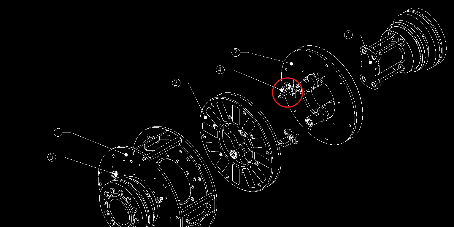
The Design
The design of the switch can be seen here, with the swinging element (5), spring (2). These key elements were mathematical modeled as seen above by summing the angular moments of the assembly for a constant rotational velocity..

Testing and Validation
The coupler was then prototyped, tested, and iterated on a test bed as shown here to validate that the coupler decoupled and remain so per the design requirements. As a result, this idea was patented under US 6,577,037